This is actually an automatic traffic control system. But here, we are providing a highest priority to ambulance. It is done by clearing the path for its easy passage, by controlling traffic control signal light systems in junctions. Several attempts have been made to design efficient automated systems to solve this problem. Most present day systems use pre-determined timing circuits to operate traffic signals. However these systems are inefficient because they do not operate according to the current volume of traffic at the crossing. It is often seen in todays automated traffic control systems that the ambulances/emergency vehicle getting caught up by a Red traffic signal and wasting valuable time. To solve this problem and we propose the idea of automatic traffic controller for ambulance emergency. Here differential priorities can be assigned to vehicles such as ambulances, fire engine, and other emergency vehicles. Here we design an intelligent signal controller which has the facility to receive RF signals. The signal contains the information of the direction they want to travel.
TRANSMITTER SECTION
SELECTION KEYS
Here four selection switches are used, corresponding to each direction i.e. NORTH, EAST, WEST or SOUTH. The person in the vehicle can select the direction they want to travel by pressing any one of the switches.
Here four selection switches are used, corresponding to each direction i.e. NORTH, EAST, WEST or SOUTH. The person in the vehicle can select the direction they want to travel by pressing any one of the switches.
ARDUINO
It is the central processing unit, which controls all the functions of other blocks in this system. ARDUINO takes or read data from selection keys and controls all the functions of the whole system by manipulating these data.
It is the central processing unit, which controls all the functions of other blocks in this system. ARDUINO takes or read data from selection keys and controls all the functions of the whole system by manipulating these data.
ENCODER
The purpose of digital encoders is for security. Any digital data is first converted to a coded form before sending wirelessly to get ensure data integrity from noises and offers security form other faulty messages. The encoded data is decoded in the receiver side and the original data is recovered. Here encoder receives data input from the MCU and convert it into a coded output signal. This coded output is corresponds to a particular direction.
The purpose of digital encoders is for security. Any digital data is first converted to a coded form before sending wirelessly to get ensure data integrity from noises and offers security form other faulty messages. The encoded data is decoded in the receiver side and the original data is recovered. Here encoder receives data input from the MCU and convert it into a coded output signal. This coded output is corresponds to a particular direction.
RF TRANSMITTER
RF transmitter is used here to transmit the selected direction details. So the data is digital encoded form and the RF transmitter module should have the capability of transmitting digital data. The data rate for the address selection operation is very slow, so a slow speed high range RF module is preferred for the application. The popular low speed RF modules are mainly based on ASK/FSK technology. In this RF system, the digital data is represented as variations in the amplitude of carrier wave. This kind of modulation is known as Amplitude Shift Keying (ASK). These are available in market at a carrier frequency of 353/ 433 MHz
RF transmitter is used here to transmit the selected direction details. So the data is digital encoded form and the RF transmitter module should have the capability of transmitting digital data. The data rate for the address selection operation is very slow, so a slow speed high range RF module is preferred for the application. The popular low speed RF modules are mainly based on ASK/FSK technology. In this RF system, the digital data is represented as variations in the amplitude of carrier wave. This kind of modulation is known as Amplitude Shift Keying (ASK). These are available in market at a carrier frequency of 353/ 433 MHz
RECEIVER SECTION
RF RECEIVER
The transmitted data is received by an RF receiver operating at the same frequency as that of the transmitter. Amplitude shift keying (ASK) is used in this project. Amplitude-shift keying (ASK) is a form of modulation that represents digital data as variations in the amplitude of a carrier wave.
The amplitude of an analog carrier signal varies in accordance with the bit stream (modulating signal), keeping frequency and phase constant. The level of amplitude can be used to represent binary logic 0s and 1s. We can think of a carrier signal as an ON or OFF switch. In the modulated signal, logic 0 is represented by the absence of a carrier, thus giving OFF/ON keying operation and hence the name given.
Transmission through RF is better than IR (infrared) because of many reasons. Firstly, signals through RF can travel through larger distances making it suitable for long range applications. Also, while IR mostly operates in line-of-sight mode, RF signals can travel even when there is an obstruction between transmitter & receiver. Next, RF transmission is more strong and reliable than IR transmission. RF communication uses a specific frequency unlike IR signals which are affected by other IR emitting sources.
DECODER
A decoder is a device which does the reverse of an encoder, undoing the encoding so that the original information can be retrieved. The same method used to encode is usually just reversed in order to decode. In digital electronics, a decoder can take the form of a multiple-input, multiple-output logic circuit that converts coded inputs into coded outputs, where the input and output codes are different. e.g. n-to-2n, binary-coded decimal decoders. Decoders are used in counter system, analog to digital converters and the output can be used to drive display system.
It accepts data from RF receiver and compares received address with its own address. If it matches, the decoder decodes the data and provides it to MCU.
ARDUINO
Arduino is an open source computer hardware and software company, project, and user community that designs and manufactures single-board microcontrollers and microcontroller kits for building digital devices and interactive objects that can sense and control objects in the physical world. The project's products are distributed as open-source hardware and software, which are licensed under the GNU Lesser General Public License (LGPL) or the GNU General Public License (GPL),[1] permitting the manufacture of Arduino boards and software distribution by anyone. Arduino boards are available commercially in preassembled form, or as do-it-yourself (DIY) kits.
Arduino board designs use a variety of microprocessors and controllers. The boards are equipped with sets of digital and analog input/output (I/O) pins that may be interfaced to various expansion boards (shields) and other circuits. The boards feature serial communications interfaces, including Universal Serial Bus (USB) on some models, which are also used for loading programs from personal computers. The microcontrollers are typically programmed using a dialect of features from the programming languages C and C++. In addition to using traditional compiler toolchains, the Arduino project provides an integrated development environment (IDE) based on the Processing language project.
The Arduino project started in 2003 as a program for students at the Interaction Design Institute Ivrea in Ivrea, Italy,[2] aiming to provide a low-cost and easy way for novices and professionals to create devices that interact with their environment using sensors and actuators. Common examples of such devices intended for beginner hobbyists include simple robots, thermostats, and motion detectors.
The name Arduino comes from a bar in Ivrea, Italy, where some of the founders of the project used to meet. The bar was named after Arduin of Ivrea, who was the margrave of the March of Ivrea and King of Italy from 1002 to 1014.[3]
ARDUINO receives a digital data, which is corresponds to the direction that the emergency vehicle wants to travel. When ARDUINO receives input from the decoder it controls the traffic light.
.
.
WORKING
Automatic traffic controller for ambulance emergency is a system which is used to overcome the limitation of currently used automatic signal controller. It is often seen in todays automated signal control systems that the ambulances/emergency vehicle getting caught up by a Red traffic signal and wasting valuable time. Thus we designed this system for providing higher priority to ambulance/emergency vehicle.
Transmitter section:
This intelligent signal controller consists of a transmitter section and a receiver section. The transmitter section is placed in the emergency vehicle. It consists of a selection switch, MCU, encoder and an RF transmitter. Here four selection keys are required. Each represents the four directions such as NORTH, EAST, WEST and SOUTH. The person in the vehicle can select one of the switches corresponds to a particular direction that they want to travel. MCU reads data from the selection keys and gives corresponding digital output to an encoder. It encodes one of the active inputs to a coded binary output. RF transmitter transmits this coded binary output from the encoder. Here we use the popular ASK modulation technique. In this RF system, the digital data is represented as variations in the amplitude of carrier wave. This kind of modulation is known as Amplitude Shift Keying (ASK).
Receiver section:
Receiver section consists of an RF receiver, RF decoder, MCU, time display and a light interface. RF receiver receives the coded binary data transmitted by the RF transmitter and given to the RF decoder. RF decoder decodes the input and gives four bit digital data to the MCU only if the address bit of encoder and decoder matches. An LED indication is used here, when match is found LED starts glowing. MCU receives a digital data, which is corresponds to the direction that the emergency vehicle wants to travel. When MCU receives input from the decoder it controls the traffic light through light interface. Control of traffic light is done by using relays, which is possible through relay interface. At the same time MCU controls the time display also. Seven-segment LED display is used here for time display. This displays the time in seconds. For that particular time period, the ambulance will get a GREEN signal for its easy passage.
CIRCUIT DIAGRAM

CIRCUIT DIAGRAM EXPLANATION
SELECTION KEYS
Selection keys are used here for the selection of appropriate direction in the coming junction for the ambulance driver. He must have very well knowledge about the direction to be travelled. ON/ OFF switches are used here as selection keys. By the mechanical operation of these keys help the driver to select the direction. 100 K resistors are used here to interface the switches to the MCU. SW1, SW2, SW3 and SW4 are connected to RA0, RA1, RA2 and RA3 respectively.
ARDUINO
ARDUINO
The Arduino UNO is a microcontroller board based on the ATmega328. It is made of 14 digital input output pins in which 6 can be used as PWM outputs. And also it has 6 analog inputs ,a 16 Mhz ceramic resonator, a USB ]connection, a power pack ,and a reset button. It has everything needed to support the microcontroller. It is so simple that it is to be connected to computer with a USB cable or power it with a AC- to DC adaptor or battery to get started.
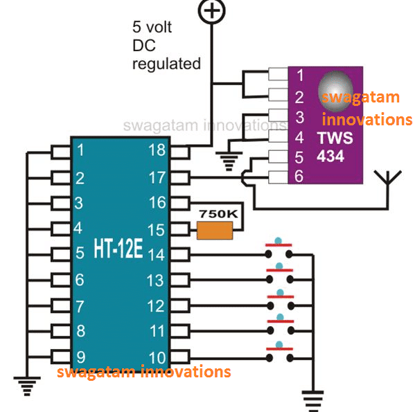
RF ENCODER
HOLTEK 212 serial encoder is used here having 8 address pins and 4 address/ data pins. The data from MCU is given to the D0, D1, D2 and D3. Here we selected the address as an 8 bit ZERO. So the pins A0 to A7 are connected to the ground.
A 1 M resistor is used to produce the desired interval oscillation in the HT12E as per the directions from data sheet. The serial form of the 12 bit encoded data contains 8 address bits and 4 data bits are given to RF transmitter through the pin Dout (pin 17).
A 1 M resistor is used to produce the desired interval oscillation in the HT12E as per the directions from data sheet. The serial form of the 12 bit encoded data contains 8 address bits and 4 data bits are given to RF transmitter through the pin Dout (pin 17).
HT12A/HT12E 212 Series of Encoders
The 212 encoders are a series of CMOS LSIs for remote control system applications. They are capable of encoding information which consists of N address bits and 12_N data bits. Each address/ data input can be set to one of the two logic states. The programmed addresses/data are transmitted together with the header bit via an RF or an infrared transmission medium upon receipt of a trigger signal. The capability to select a TE trigger on the HT12E or a DATA trigger on the HT12A further enhances the application flexibility of the 212 series of encoders. The HT12A additionally provides a 38 kHz carrier for infrared systems
RF TRANSMITTER
A 433 MHz RF transmitter is used here has the communication technique of ASK. A 17.2 cm length single strand wire is used as antenna. The encoded data is digitally modulated and transmitted by the module.
EXPLANATION
RF transmitter is used to transmit the receiver selection details. So the data is digital encoded form and the RF transmitter module should have the capability of transmitting digital data. We used very popular ASK transmitter module. This is operating at 433 MHz at a maximum bit transfer rate of 3 kbits/ second. The company offers a range of 60 meter indoor. They widely used in remote control applications. The TX module is available in a simple package and pin output. They always accept data in serial format but can be directly connected to data out pin of HT12E. Their performance with HT12 E /HT12D pair is excellent. They are coming in 4pin hybrid package pins are for VCC, GND and data in and antenna out. The length is recommended 17.2 cm and insulated copper wire serves as the antenna.
POWER SUPPLY
The above circuit is the power supply unit of this section. It consists of a 12 V battery, voltage regulator IC 7805 and capacitors as filters. This circuit can provide fixed +5V.
IC voltage regulators
The power supply is the most indispensible part of any 00project. IC regulators are versatile and relatively inexpensive. The regulated circuit is used to maintain constant output level. The integrated circuit regulator, some time called the three terminal regulators contains the circuitry of reference source error amplitude control device and overloaded protection all in a single IC chip. They are connected between output of the filter and input of the load.
The 78xx series consist of three terminal +ve voltage regulators. With adequate heat sinking they can deliver output current in excess of 1A. For proper operation, there should be a common ground between the input and output voltages.
Voltage regulators comprise a class of widely used ICs. Regulator IC units contain the circuitry for reference source, comparator amplifier, control device, and overload protection all in a single IC. IC units provide regulation of either a fixed positive voltage, a fixed negative voltage, or an adjustably set voltage. The regulators can be selected for operation with load currents from hundreds of milli amperes to tens of amperes, corresponding to power ratings from milli watts to tens of watts.
A fixed three-terminal voltage regulator has an unregulated dc input voltage, Vi, applied to one input terminal, a regulated dc output voltage, VO, from a second terminal, with the third terminal connected to ground.
The series 78 regulators provide fixed positive regulated voltages from 5 to 24 volts. Similarly, the series 79 regulators provide fixed negative regulated voltages from 5 to 24 volts.
RECEIVER SECTION
RF RECEIVER
A 433 MHz ASK RF receiver is used in this system. The demodulated data in the serial form is connected to the RF decoder to its pin Din (17).
RF DECODER
HOLTEK 212 serial decoder is used here. In this section we set the address of the decoder is as similar as that of encoder. So the 8 address pins are grounded. If the decoder receives the data with same address bits then the pin 14 (VT) become high. We get the decoded data in parallel form at D0 to D3 pin which is directly connected to RA0 to RA3 pins of the MCU respectively.
If there is no signal received by HT12D then VT is at low and the transistor BC 547 does not conduct. If a data with same address sequence is received or the decoder is ready to transfer 4 bit parallel data to MCU then VT becomes high, transistor conducts and the LED glows. This makes a logic transition at the RA4 pin of MCU which is connected to the output of transistor. This LED indication is also used here for the visual indication of data reception.
If there is no signal received by HT12D then VT is at low and the transistor BC 547 does not conduct. If a data with same address sequence is received or the decoder is ready to transfer 4 bit parallel data to MCU then VT becomes high, transistor conducts and the LED glows. This makes a logic transition at the RA4 pin of MCU which is connected to the output of transistor. This LED indication is also used here for the visual indication of data reception.
COMPONENT EXPLANATION
LED
A light-emitting diode (LED) is an electronic light source. All early devices emitted low-intensity red light, but modern LEDs are available across the visible, ultraviolet and infra red wavelengths, with very high brightness.
LEDs are based on the semiconductor diode. When the diode is forward biased (switched on), electrons are able to recombine with holes and energy is released in the form of light. This effect is called electroluminescence and the color of the light is determined by the energy gap of the semiconductor. The LED is usually small in area (less than 1 mm2) with integrated optical components to shape its radiation pattern and assist in reflection
BC 547:
This NPN transistor is designed for use as general purpose amplifiers and switches requiring collector currents to 300 mA.
POWER SUPPLY
The ac voltage, typically 220V rms, is connected to a transformer, which steps that ac voltage down to the level of the desired dc output. A diode rectifier then provides a full-wave rectified voltage that is initially filtered by a simple capacitor filter to produce a dc voltage. This resulting dc voltage usually has some ripple or ac voltage variation.
A regulator circuit removes the ripples and also remains the same dc value even if the input dc voltage varies, or the load connected to the output dc voltage changes. This voltage regulation is usually obtained using one of the popular voltage regulator IC units.
PROGRAM FOR EMERGENCY TRAFFIC CONTROL
int L1[] = {11,12,13}; // Lane 1 Red, Yellow and Green
int L2[] = {8,9,10}; // Lane 2 Red, Yellow and Green
int L3[] = {5,6,7}; // Lane 3 Red, Yellow and Green
int L4[] = {2,3,4}; // Lane 4 Red, Yellow and Green
int a=0, b=0, c=0, d=0;
unsigned long int pmillis, prevmillis ;
void setup()
{
pinMode(A0, INPUT);
pinMode(A1, INPUT);
pinMode(A2, INPUT);
pinMode(A3, INPUT);
for (int i = 0; i < 3; i++)
{
pinMode(L1[i], OUTPUT);
pinMode(L2[i], OUTPUT);
pinMode(L3[i], OUTPUT);
pinMode(L4[i], OUTPUT);
}
for (int i = 0; i < 3; i++)
{
digitalWrite(L1[i], LOW);
digitalWrite(L2[i], LOW);
digitalWrite(L3[i], LOW);
digitalWrite(L4[i], LOW);
}
pmillis=millis();
}
void loop()
{
//------------------------------------------------WHEN AMBULANCE ARRIVES------------------------------------------------
if(digitalRead(A0)==LOW){a=1; prevmillis = millis();}
if(digitalRead(A1)==LOW){b=1; prevmillis = millis();}
if(digitalRead(A2)==LOW){c=1; prevmillis = millis();}
if(digitalRead(A3)==LOW){d=1; prevmillis = millis();}
while((a==1 || b==1 || c==1 || d==1) && (millis()-prevmillis<10000)){
for (int i = 0; i < 3; i++)
{
digitalWrite(L1[i], LOW);
digitalWrite(L2[i], LOW);
digitalWrite(L3[i], LOW);
digitalWrite(L4[i], LOW);
}
if(a==1){
digitalWrite(L1[2], HIGH);
digitalWrite(L3[0], HIGH);
digitalWrite(L4[0], HIGH);
digitalWrite(L2[0], HIGH);
}
if(b==1){
digitalWrite(L1[0], HIGH);
digitalWrite(L3[2], HIGH);
digitalWrite(L4[0], HIGH);
digitalWrite(L2[0], HIGH);
}
if(c==1){
digitalWrite(L1[0], HIGH);
digitalWrite(L3[0], HIGH);
digitalWrite(L4[2], HIGH);
digitalWrite(L2[0], HIGH);
}
if(d==1){
digitalWrite(L1[0], HIGH);
digitalWrite(L3[0], HIGH);
digitalWrite(L4[0], HIGH);
digitalWrite(L2[2], HIGH);
}
}
if ((a==1 || b==1 || c==1 || d==1) && millis()-prevmillis>=10000){
for (int i = 0; i < 3; i++)
{
digitalWrite(L1[i], LOW);
digitalWrite(L2[i], LOW);
digitalWrite(L3[i], LOW);
digitalWrite(L4[i], LOW);
pmillis=millis();
a=b=c=d=0;
}
}
//------------------------------------------------ORDINARY SIGNAL------------------------------------------------
if ((millis()-pmillis)<=7000){
digitalWrite(L1[2], HIGH);
digitalWrite(L3[0], HIGH);
digitalWrite(L4[0], HIGH);
digitalWrite(L2[0], HIGH);
}
if ((millis()-pmillis)>7000 && (millis()-pmillis)<=10000){
digitalWrite(L1[2], LOW);
digitalWrite(L3[0], LOW);
digitalWrite(L1[1], HIGH);
digitalWrite(L3[1], HIGH);
}
if ((millis()-pmillis)>10000 && (millis()-pmillis)<=17000){
digitalWrite(L1[1], LOW);
digitalWrite(L3[1], LOW);
digitalWrite(L1[0], HIGH);
digitalWrite(L3[2], HIGH);
}
if ((millis()-pmillis)>17000 && (millis()-pmillis)<=20000){
digitalWrite(L3[2], LOW);
digitalWrite(L4[0], LOW);
digitalWrite(L3[1], HIGH);
digitalWrite(L4[1], HIGH);
}
if ((millis()-pmillis)>20000 && (millis()-pmillis)<=27000){
digitalWrite(L3[1], LOW);
digitalWrite(L4[1], LOW);
digitalWrite(L3[0], HIGH);
digitalWrite(L4[2], HIGH);
}
if ((millis()-pmillis)>27000 && (millis()-pmillis)<=30000){
digitalWrite(L4[2], LOW);
digitalWrite(L2[0], LOW);
digitalWrite(L4[1], HIGH);
digitalWrite(L2[1], HIGH);
}
if ((millis()-pmillis)>30000 && (millis()-pmillis)<=37000){
digitalWrite(L4[1], LOW);
digitalWrite(L2[1], LOW);
digitalWrite(L4[0], HIGH);
digitalWrite(L2[2], HIGH);
}
if ((millis()-pmillis)>37000 && (millis()-pmillis)<=40000){
digitalWrite(L1[0], LOW);
digitalWrite(L2[2], LOW);
digitalWrite(L1[1], HIGH);
digitalWrite(L2[1], HIGH);
}
if ((millis()-pmillis)>40000){
digitalWrite(L2[1], LOW);
digitalWrite(L1[1], LOW);
pmillis=millis();
}
}
Comments
Post a Comment